Minimal MBR in Assembly
After the BIOS firmware is done with all its initialization routines, and validations, it loads code from the first sector on disk into memory address 0x7c00.
The instruction pointer is also set to 0x7c00. Meaning, the CPU starts executing code at that address.
In this very rudimentary MBR section, we’ll try to write a string (“Hello world!”) to the screen via the VGA Text Buffer
VGA Text Buffer and MMIO
The VGA Text Buffer is a memory mapped I/O buffer which means the firmware reserves a memory address and map it to a given I/O device, instead of physical RAM on your computer.
When you access this address, the CPU takes that request and instead of treating it like any other memory operation, it routes that request to the given I/O devices.
In case of VGA Text Buffer, the physical memory address 0xB8000 is reserved by the firmware and is mapped to the Video Graphics Array.
When reading, it doesn’t really return anything meaningful, so the CPU just receives a bunch of zeros. However, writing to that address gives us a powerful tool to display text on the screen.
When you write data to this buffer in a specific format, text characters show up on the screen. (we’ll discuss that format briefly in a bit)
Thus, our goal is to write bytes to this address (and a few subsequent addresses), so that our desired output shows up on the screen.
Keep in mind that this only works with BIOS. UEFI doesn’t natively support it.
VGA Text Buffer cell format
The format is relatively simple. The VGA Text buffer is a linear buffer with 2000 cells arranged in a 80x25 character grid.
Each character is made up of two bytes.
The least significant byte represents the ASCII character code of the character. Well.. not exactly ASCII. It uses a special set of characters called the Code Page 437. This set is mostly compatible with ASCII but it adds a bunch of additional glyphs above 128 characters. Since there are only 8 bits available to us, we get a total of 256 characters to work with, including 128 ASCII characters and 128 additional glyphs.
The most significant byte defines how the character looks i.e, it controls its foreground color, its background color, and blinking behavior.
The most significant nybble of the byte (i.e first four bits from left) represents the background color.
and the least significant nybble (i.e last four bits from the left) represents the foreground color.
The most significant bit (i.e the first bit from left) is also repurposed as a blinking bit which makes the character blink at 1-2 Hz (Although it needs to be configured via the Attribute Control register).
The color table itself looks like this (Thank you OS Dev Wiki for providing this):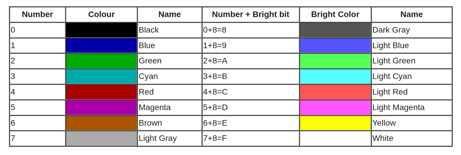
In essence a single VGA Text Buffer cell looks like this.

Writing to MMIO
In order to see our desired text on the screen, we will write bytes to memory starting at the VGA MMIO address 0xb8000
This is how the memory buffer should look like after we’re done with it.
| Address (Base) | Character | Background Color (Base + 8 bits) | Foreground Color (Base + 8 bits + 4 bits) |
|---|---|---|---|
| 0xb8000 | H | Black | Green |
| 0xb8002 | e | Black | Green |
| 0xb8004 | l | Black | Green |
| 0xb8006 | l | Black | Green |
| 0xb8008 | o | Black | Green |
| 0xb800a | (Space) | Black | Green |
| 0xb800c | W | Black | Green |
| 0xb800e | o | Black | Green |
| 0xb8010 | r | Black | Green |
| 0xb8012 | l | Black | Green |
| 0xb8014 | d | Black | Green |
| 0xb8016 | ! | Black | Green |
| 0xb8017..END | (Space) | Black | Green |
💡 Buffer layout
The VGA buffer is laid out in such a way that the first address refers to the top left cell of the 80x25 grid
Subsequent addresses move right until 80 columns are used up, and moves to the first column of the next row.
Abstracting the behavior that we need
To get a clear idea of what we are trying to do, let’s write some pseudo code that mimics the behavior that we want.
 1// 80x25 cells is the standard VGA Text buffer resolution
 2width = 80
 3height = 25
 4
 5// VGA text buffer is memory mapped, starting at physical address `0xb8000`
 6vga_buffer_start = 0xb8000
 7cell_count = width * height
 8vga_buffer_end = vga_buffer_start + (cell_count * 2) // each cell is 2 bytes in length
 9
10background = 0x0 // 0 is Black (refer to the color palette table above)
11foreground = 0x2 // 2 is Green (refer to the color palette table above)
12
13// VGA text mode packs the foreground and background colors into a single byte.
14// the background uses the upper four bits, so we shift it left by four positions.
15// this aligns it correctly and guarantees that the lower four bits are empty
16// i.e they're set to zero for so that the foreground can occupy those bits.
17normalized_background = background << 4
18
19attribute = normalized_background | foreground
20characters = ['H', 'e', 'l', 'l', 'o', ' ', 'W', 'o', 'r', 'l', 'd', '!']
21
22address = vga_buffer_start
23
24// Write Text
25for character in characters {
26    memory[address] = character
27    memory[address + 1] = attribute
28    address += 2
29}
30
31// Cleanup Rest (set everything to empty space)
32while address < vga_buffer_end {
33    memory[address] = ' '
34    memory[address + 1] = attribute
35    address += 2
36}
Bootloader Assembly
Before we translate our pseudo code over to assembly, we need to understand a few things.
Specifically, we need to know about the CPU instructions we will use and their relevant CPU registers, and additionally, we need to know how the CPU handles memory addresses.
Let’s first talk about how the CPU gets to a given memory location.
Calculating the Memory location
In the original 8086 architecture, Intel wanted to reduced instruction size, simplify decoding of the instructions, and enabled efficient memory streaming. So they thought it would be a good idea to hard wire operands to a bunch of instructions, such that whenever the CPU encounters those instructions, it can assume that the operands are present in those hard wired registers
Two such instructions we will use are
lodsbandstosw. These instructions are architecturally hard-wired to specific registers:
lodsbloads a byte from memory at the segment and offset pair defined by thedsandsiregisters.stoswstores a word from memory at the segment and offset pair defined by theesanddiregisters.The
es/di,ds/siare special registers that thelodsbandstoswinstructions are hard wired to use.The
lodsbinstruction uses thedsandsiregisters as the data segment and offset registers respectively, and similarly, thestoswinstruction uses theesanddiregisters as the data segment and offset registers respectively.What is data segment and offset?
On the 8086, memory addresses are formed using segmented addressing. A physical address is computed by shifting the segment register left by four bits (multiplying by 16) and adding the offset, like so:
physical_address = ((data_segment << 4) + offset) & 0xfffffThe data segment register is shifted left by 4 bits to allow the CPU to address up to 1 MiB (2^20 bytes) of memory, even though individual segment offsets are limited to 64 KiB (2^20 bytes).
That extra
& 0xfffffis to signify that the addresses above 1MiB are wrapped around, because 8086 only has a 20 bit address bus.In our case, we need to get to the physical address
0xb8000so we need to configure our output registers such that:
(data_segment << 4) + offset & 0xfffff = 0xb8000We can do this simply by setting our offset to zero, and dividing our base address by 16. Our VGA base is cleanly divisible by 16 so it works out in our favor. In order to address the subsequent bits, we can just increment the offset register by one.
Concretely speaking, when we write to the buffer, we’d have to put
0xb8000 / 16(or0xb800) in the data segment register, and the 0 in the offset register (which we’ll increment when we need to address subsequent addresses like0xb8001,0xb8002, etc.)Similarly, in when reading the string that we want to write we’ll read it from the segment present within our code itself hence the data segment must be set to the start of our code i.e
0x7c00, and the offset must be set to wherever our string lies in memory.
The instructions we’ll use
lodsb - Load String Byte
The lodsb instruction loads one byte from the location defined by
ds:sisegment pair and puts it in a register called thealregister. It then moves thesiregister by 1 byte in the direction defined by the direction flag, which can either be 0 (to represent an increment) or 1 (to represent a decrement).The direction flag is a flag present at the 10th bit in the 16 bit
FLAGSregister used to define a left-to-right or right-to-left direction. For our purpose, it must be set to 0 to signify an increment.
stosw - Store String Word
The stosw instruction can be thought of as the opposite of the lodsb instruction. It stores a word (2 bytes, in x86) from the
axregister and puts it in the memory location defined by thees:disegment pair. Then it moves thediregister by 1 word i.e 2 bytes (based on the direction flag, in our case, +2).We use the stosw instead of the stosb since we need to write two bytes for one cell, one character byte and one attribute. The stosw instruction writes the entire contents of the
axregister (16 bits / 1 word) to the given memory address. We’ll pack the character and attribute bytes in the upper and lower 8 bit halves of theaxregister, hence we’ll be able to write a full character along with its attribute byte, in one single instruction, instead of writing a character byte and then subsequently writing an attribute byte (using 2 separate instructions).
The registers we need to know about
AX register (ax, ah, al)
It is a 16 bit general purpose register that can be used to store arbitrary data. The aforementioned instructions are hard wired to used it to load and store data. For our purposes we will use it as a negotiator between our memory and the VGA buffer.
The
axregister itself is broken down into two smaller 8 bit registers namelyahandalwhich refer to the higher (most significant) 8 bits and lower (least significant) 8 bits of theaxregister respectively
ES, DI, DS, SI registers
esanddsare segment registers which are used to store the base address of an address translation, anddiandsiare registers that are used to store the destination and source index of that same segment address translation.
CS register
The code segment register is a specialized 16 bit register that stores the segment of the currently executing instructions/code
CX register
The CX register is a general purpose register which is primarily used as a counter. The
loopinstruction relies on thecxregister to determine how many times it should execute.
The assembly code
With that, I think we are ready to write our first bits of assembly code for our minimal MBR section.
  1; this is not an instruction but rather
  2; it is an assembler directive which tells
  3; the assembler to assume that the code is loaded starting at 0x7c00
  4; this is done to ensure that any dynamic calculations such as `$` (current address) etc
  5; resolve to the correct value
  6[org 0x7c00]
  7
  8; since we are in real mode, we can't use more than 16 bits
  9; so we make sure to emit instructions in 16 bits using 16 bit instruction encoding.
 10bits 16
 11
 12FOREGROUND equ 0x2 ; Green
 13BACKGROUND equ 0x0 ; Black
 14
 15NORMALIZED_BACKGROUND equ (BACKGROUND << 4)
 16
 17ATTRIBUTE equ FOREGROUND | NORMALIZED_BACKGROUND
 18
 19VGA_BUFFER_WIDTH equ 80
 20VGA_BUFFER_HEIGHT equ 25
 21
 22CELL_COUNT equ VGA_BUFFER_WIDTH * VGA_BUFFER_HEIGHT
 23
 24; This is the initial setup phase of our program where we set things up such as
 25; initial memory address to read from (`si` or source index)
 26; and the destination address (`di` or destination index) to write to
 27; (both via segmented addressing).
 28.set_initial_memory_addresses:
 29    ; As discussed earlier we set the value of the data segment of our source (our string)
 30    ; equal to the start of our program (i.e the value in code segment register).
 31    ;
 32    ; We can't directly load an immediate value in the `ds` register so we
 33    ; first load the value in an intermediate register (`ax`) and then perform a
 34    ; register to register move operation from `ax` to `ds`.
 35    ; ds <- ax <- cs
 36    mov ax, cs ; 👈 load base address i.e where our program itself is placed in memory (`0x7c00`) into `ax`
 37    mov ds, ax ; 👈 then move from `ax` to `ds`
 38
 39    ; Similarly, the `stosw` instruction will use the `es:di` segment pair
 40    ; so we set the base i.e the segment register in that pair equal to the VGA base.
 41    ;
 42    ; We'll use the destination index register (`di`) to write to subsequent addresses
 43    ; in that buffer.
 44    ;
 45    ; We use a similar method to load the value into `es`
 46    ; i.e load value into `ax` and then move from `ax` to `es`.
 47    ; es <- ax <- 0xb800
 48    mov ax, 0xb800 ; 👈 load VGA base address into `ax`
 49    mov es, ax ; 👈 then move from `ax` to `es`
 50
 51    ; Since we start by writing to the 0th address in the VGA buffer,
 52    ; we initially set the destination index (`di`) register to zero.
 53    ;
 54    ; We will increment the `di` register per iteration as we keep
 55    ; writing our string to the VGA buffer.
 56    ;
 57    ; We use `xor` instruction instead of manually setting it to zero since for the
 58    ; purpose of zeroing, `xor` is generally faster.
 59    xor di, di
 60
 61    ; We clear the direction flag to make sure that when the CPU encounters
 62    ; any instructions that move the `si`/`di`/`cx` registers, it moves them
 63    ; in the right direction i.e increment (as opposed to decrement, if the flag is set).
 64    cld
 65
 66
 67.initialize_data_source:
 68    ; We move the address of the start of our message in the source index register (`si`).
 69    ;
 70    ; Along with the `ds` register that we loaded earlier, we form a complete source address as the following:
 71    ;
 72    ; ds (set to start of our program, 0x7c00, defined by the `cs` register)
 73    ;                                     +
 74    ; si (set to start of our string, dynamically calculated by the assembler at compile time)
 75    mov si, message
 76
 77.setup_write_text:
 78    ; Since the VGA buffer uses the upper half of a word as the attribute byte,
 79    ; we fix the upper half of the `ax` register i.e the `ah` register to our attribute byte.
 80    ;
 81    ; While writing to the VGA buffer, even though we'll move the entire contents of the `ax` register
 82    ; to the memory buffer, we'll only update the lower half (`al`) of it in order to change the characters
 83    ; being written to the screen, while keeping the `ah` intact.
 84    ;
 85    ; Which means, we can set the value in the `ah` register just once (during this initialization phase)
 86    ; and forget about it
 87    mov ah, ATTRIBUTE
 88
 89    ; We set up a counter so that we only iterate a fixed number of times (# of iterations = # of characters).
 90    mov cx, message_len
 91
 92; We repeatedly read from the address `ds:si`, load it into `al` (lower half of the ax register)
 93; and then write the `ax` register in its entirety to the address `es:di`
 94;
 95; The `ax` register contains our character in its lower half that we just loaded using the `lodsb` instruction
 96; as well as the attribute byte in its upper half, that we loaded manually earlier.
 97;
 98; The `loop` instruction repeats this block until the `cx` register hits zero.
 99.perform_write_text:
100    lodsb
101    stosw
102    loop .perform_write_text
103
104; We setup a clear function in a similar manner, by setting up a counter that is equal to the number of
105; bytes remaining in the VGA buffer after we've written our string.
106;
107; We also store a fixed character in our `al` register since we have to only write empty text to the buffer.
108;
109; We don't have to make any changes to the `ah` register, since it already contains the attribute byte
110; that we had set earlier.
111.setup_clear:
112    mov cx, (CELL_COUNT - message_len)
113    mov al, ' '
114
115; Similar to our `perform_write_text` function, we do pretty much the same thing here but
116; instead of reading a different character from memory in each iteration, we use a fixed
117; empty space character. This makes our code even more simplified due to the fact that most
118; of the operands have already been set (an empty space in `al`, and our attribute byte in `ah`),
119; so now, we don't even have to load anything. Just write, and increment until the counter hits zero.
120.perform_clear:
121    stosw
122    loop .perform_clear
123
124; At the end of our program, we tell the CPU to stop doing anything.
125.hang:
126    hlt
127    jmp .hang
128
129; this is our string
130; we use the `db` instruction to write the string "Hello world!" verbatim in the binary itself
131; when this binary is loaded into memory the `message` label will have the memory address of this string
132; (which is dynamically calculated by the assembler)
133message db "Hello world!"
134message_len equ $ - message
135
136; we write a bunch of zeros to the rest of our binary (except the last two bytes)
137times 510 - ($ - $$) db 0
138
139; lastly, to make sure our firmware is happy, we write the validation word `0xAA55` at address 511 and 512
140dw 0xAA55
Let’s go back to our main post and continue there.